

1. What is a power management chip (PMIC)?
Each country has its own civil power source, also called alternating current (AC), and in Vietnam, the standard voltage is usually 220V. In order to supply power to electronic devices at home, that AC power source is converted into direct current power source (DC) and then transmitted to the electronic circuits within the devices.
Each electronic device is equipped with numerous circuits inside with different functions and voltage level requirements. This is when the Power Management Integrated Circuit (PMIC) plays a crucial role in extracting voltage from the power source and distributing the appropriate, stable voltage, at the suitable voltage level to each circuit.
2. How does PMIC work?
The semiconductor community sometimes analogizes PMIC as much like the “heart” in the human body, “pumping” blood to organs, to keep them working in function. PMIC holds the role of the “voltage converter” that converts voltage from the battery or power source. It adjusts, coordinates, and distributes suitable voltage power to each component of the electrical circuit.

Figure 1: PMIC – The “heart” of electrical devices
PMIC handles the voltage sequencing of the power system, provides power to various loads, and protects against overvoltage, undervoltage, overcurrent, or other thermal issues. Thus, the PMIC chip enhances higher efficiency in energy management, limiting damages, and extending batteries’s lifespan in electronic devices.
3. Types of PMIC (classified by Application and Function)
PMIC’s power management scope is relatively broad, including power conversion (DC-DC, AC-DC, DC-AC), distribution and detection of power voltage, battery protection and charging, LED control, etc. Therefore, PMIC is classified into various types based on their applications and functions.
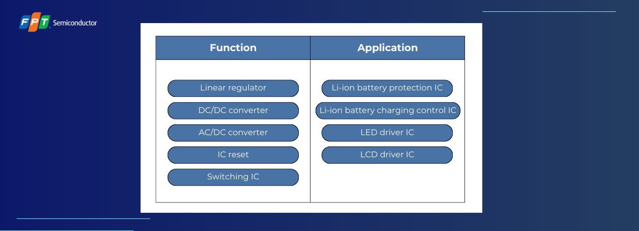
Figure 2: Power Management Integrated Circuit (PMIC) types – classified by function and application
4. The Role of Power Management Integrated Circuit (PMIC) Electronic Systems
An electronic system can be powered directly from an alternating current (AC) source powered by a battery.

Figure 3: Linear and switching voltage converting process
There are two types of direct current voltage regulators (DC): linear and switching.
Based on input, output voltage, and desired current load, semiconductor engineers choose the appropriate DC voltage for their system design.
4.1 Linear Regulator
Taking linear regulators into account, a crucial type of integrated circuit that must be mentioned is the Low Dropout (LDO) voltage regulator. It can continuously generate a stable output voltage (VOUT) when the difference between input voltage (VIN) and output voltage (VOUT) remains at a very small level.
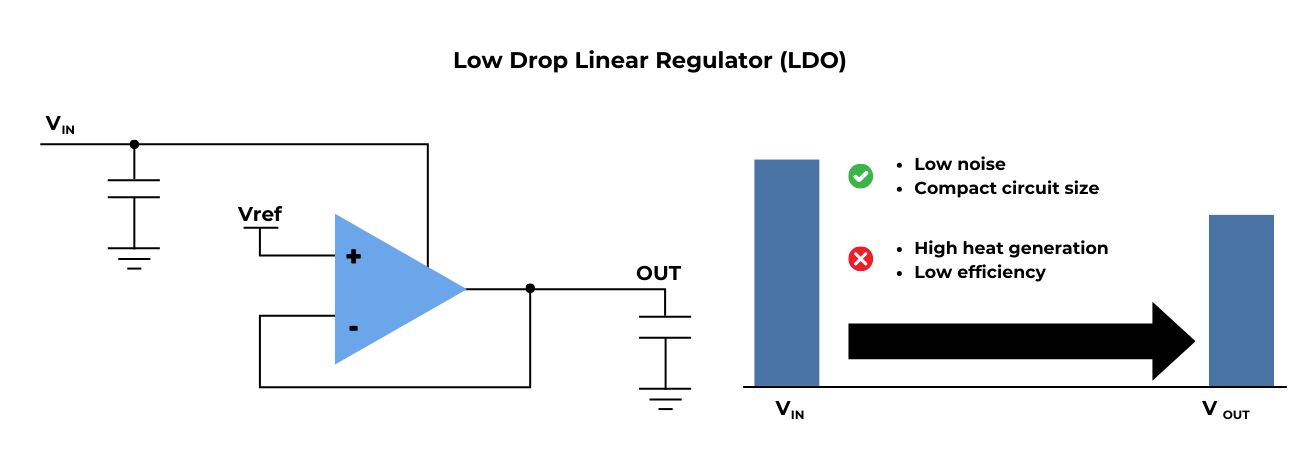
Figure 4: Low Dropout (LDO) voltage regulator
Let’s take a look into the advantages and disadvantages of LDO voltage regulator
Advantages
- No switch noise
- Smaller compact circuit size (as it doesn’t require large inductors or transformers)
- Simpler design (usually consists of a voltage reference, amplifier, and pass element).
Disadvantages
However, linear voltage regulators (LDO) generate significant heat and lower in efficiency
LDOs with low standby currents are most suitable for mobile and wireless applications.
4.2 Switching Regulator
Switching regulators convert VIN into different VOUT through a switching element, use external inductors, and capacitors to smooth the output voltage (VOUT). Switching regulators have been proven to be more efficient and can support higher output currents than linear regulators.
After the output voltage (VOUT) is adjusted, there might still be switching noise or ripple during the filtering process. Usually, switching regulators (converters) are classified based on the input-output voltage relationship
-
BUCK Converter: VOUT < VIN
The BUCK converter is a step-down voltage regulator, producing output voltage (VOUT) that is lower than the input voltage (VIN). A BUCK Converter consists of an inductor, a switching FET (Field-Effect Transistor) or diode, a capacitor, and an error amplifier with a switching control circuit.
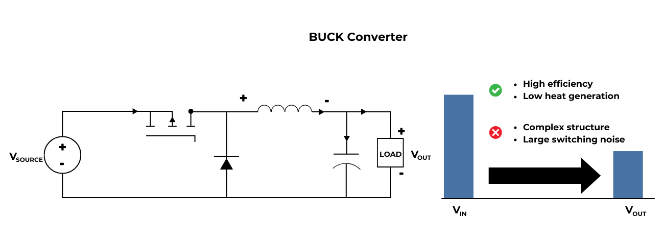
Figure 5: BUCK Converter
It operates by modulating the on-off time of the metal-oxide-semiconductor field-effect transistor (MOSFET) and supplying power to the inductor. The high efficiency of the Buck converter is generated from its MOSFET being fully turned on or off. It does not operate in the intermediate state between on and off (resistance) as in linear regulators.
The BUCK Converter generates a switching waveform in either pulse-width modulation (PWM) or pulse-frequency modulation (PFM) mode. After that, the converter filters it using external components such as capacitors and inductors outside the chip to create the output voltage (VOUT). This efficient voltage conversion method contributes to extending battery life, reducing system temperature, and allowing for compact product sizes.
BUCK Converters are utilized in various applications, namely providing power through USB connections and other peripheral devices for computers. They are also used in smartphones, tablets, mobile devices, and a wide range of other electronic devices.
-
BOOST Converter: VOUT > VIN
The Boost Converter is a boost process, regulating output voltage (VOUT) from its input voltage (VIN). For instance, the Boost Converter is proven to be beneficial when you need to increase the DC input voltage from 3.3V to an output voltage (VOUT) of 5.0V. Such voltage boosting is commonly seen in many applications using Li-ion or LiPo batteries.
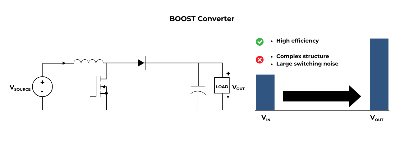
Figure 6: BOOST Converter
A BOOST Converter comprises components much similar to a resistive circuit (inductor, field-effect transistor [FET] or diode, capacitor, and error amplifier with a switch control circuit), but with different connections. It operates by adjusting the on-time of the MOSFET and supplying power to the inductor.
-
BUCK-BOOST Converter: VOUT can be flexibly adjusted (lower, higher, or equal to VIN)
The BUCK-BOOST Converter is a “switching mode converter”, combining both Buck and Boost converters’ principles into a single converter model (regulator). It is able to manage a wide range of input and output voltages. The control circuit adjusts the on-off time of the MOSFET to decrease or increase the input voltage as needed to achieve the desired output voltage (VOUT).
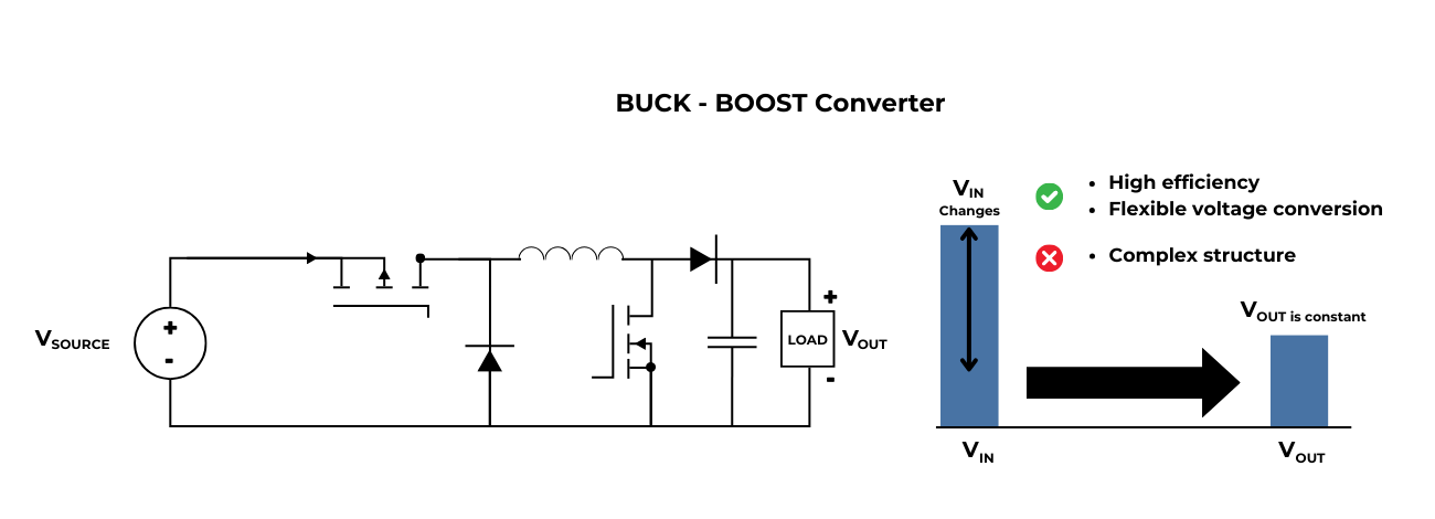
Figure 7: BUCK-BOOST Converter
5. Upcoming Trends of Power Management Integrated Circuits (PMIC)
The implementation of Power Management Integrated Circuit (PMIC) in this modern day is highly flexible, serving multiple or even all voltage regulation, functions with just a single PMIC chip. These versatile PMICs are created by connecting standardized regulators/IPs, flexibly adjusted to suit various applications. This allows for saving design costs and reducing time to market.
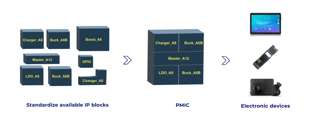
Figure 8: PMIC made from standardized IP
Furthermore, along with the driving trends of going green, consumers and businesses are now demanding for energy-saving products, minimizing environmental impact, and reducing carbon emissions. In other words, this also means that the demand for energy-efficient electronic products is predicted to increase rapidly, making optimal energy management an important and sought-after factor in the semiconductor industry.
With the advancements in this ever-changing technology industry, PMIC chips are becoming smaller and smaller, more energy-efficient, and integrating more functions. Various semiconductor enterprises are now focusing on researching and developing advanced chip lines to meet the growing global market demand.